
The DigiTrak Falcon F5 locating system supports one core task: help HDD crews locate and track a transmitter in the drill head so they can steer with confidence. A complete setup typically includes a handheld receiver (locator), a compatible transmitter, a remote display at the drill rig, and the power and telemetry hardware that keep the system running.
Falcon F5 focuses on interference management. Its documentation describes using a wide range of receiving frequencies and multiple telemetry channels so crews can work through jobsite noise instead of fighting it.
This article breaks the system into the parts crews touch every day—receiver, transmitter, remote display, and accessories—using only manufacturer manuals, spec sheets, and DCI support documentation.
Receiver: Falcon F5 handheld locator
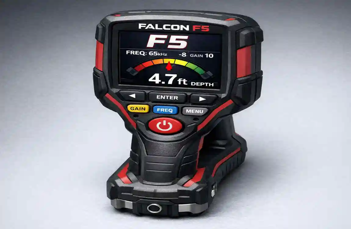
The receiver is the crew’s eyes on the bore. It reads the transmitter’s signal and turns it into locating and steering information the locating specialist can use on the ground. DCI lists the Falcon F5 receiver’s receiving frequency range as 0.33–45.0 kHz, which gives crews room to adapt when interference changes the game.
In the field, hardware specs matter because they set limits you can plan around. DCI lists the receiver with a lithium-ion battery pack, 8–12 hours of battery life, ±5% accuracy, and an operating temperature range of -4 to 140°F. It also lists a size of 11 x 5.5 x 15 in. and a weight of 8.4 lb (with battery). Those numbers tell you what the unit can handle and what you need to support—spare packs, charging discipline, and realistic expectations on extreme hot or cold days. For examples of Falcon F5 and F5+ locators, transmitters, and remote displays listed together, see the full collection here.
The Falcon F5 spec sheet also highlights receiver features aimed at precision work. It lists Full Scale Sensitive Pitch (FSSP) with 0.1% resolution through ±99.9% slope and describes MAX Mode as filtering noise to boost weak data signals and stabilize depth readings. That language is simple and practical: the receiver is built to help you keep usable depth and pitch data when conditions threaten to turn the screen into a guessing game.
Receiver performance on noisy jobsites
Interference is the reason Falcon F5 exists. DCI describes two broad interference types that show up on HDD sites: passive interference (such as rebar) and active interference (jobsite electrical noise). The Falcon F5 spec sheet calls out ultra-low “Sub-kilohertz” frequency choices in the 0.33–0.75 kHz range to address passive interference, and higher frequency options up to 45 kHz to address active interference. That range gives the locator options when one band starts producing unstable depth or weak signal quality.
The operator workflow matters as much as the hardware. The Falcon F5 Operator’s Manual describes scanning for interference, optimizing frequencies, calibrating the system, and checking Above Ground Range before drilling. Treat that sequence like a start-up checklist. It helps you catch problems while the transmitter is still accessible—before the bore turns into troubleshooting.
The receiver can also expand into documentation work with iGPS. DCI states that the DigiTrak iGPS module attaches to the Falcon F5 receiver and adds GNSS data to logged depth readings. DCI also states you can export the logged data as KML for Google Earth. That gives contractors a straightforward way to tie bore data to map-based deliverables without building a separate workflow from scratch.
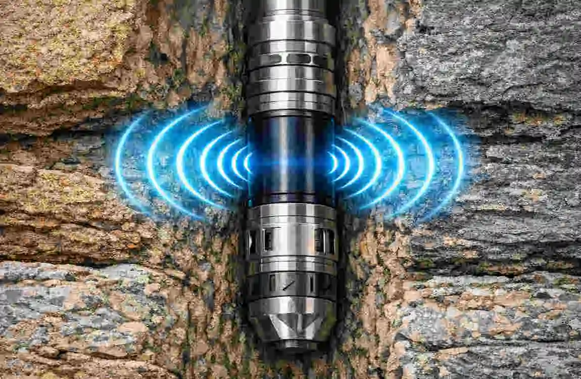
Transmitter: the downhole signal source
The transmitter lives in the drill head and does the hard part: survive the bore while sending data the receiver can trust. Falcon F5 transmitters support frequency flexibility because the ground does not stay “clean” for an entire run. DCI’s Falcon F5 transmitter overview lists transmitter models and states that FT5p/FT5Lp frequencies run from 4.5 to 45 kHz.
DCI also positions the Falcon F5 system as capable across both higher and ultra-low frequency ranges to address different interference environments. The Falcon F5 system sheet describes using wideband (4.5–45 kHz) to combat active interference and Sub-k®/Sub-k™ Rebar (0.33–0.75 kHz) to combat passive interference such as rebar. That gives the locating specialist a path forward when signal quality drops: change the band to suit the problem instead of accepting unstable data.
Falcon F5 transmitters can also deliver more than location and heading. DCI’s transmitter overview states: “The FT5 provides downhole fluid pressure monitoring up to 250 psi (1725 kPa).” That capability matters when you want visibility into downhole conditions instead of relying only on surface feel.
Finally, the transmitter is not plug-and-play in the drill head. The Falcon F5 Operator’s Manual includes transmitter housing/slot requirements and provides example minimum slot lengths for 19-inch, 15-inch, and 8-inch transmitters, along with notes that guide proper fit. Good data starts with a protected transmitter. If the housing is wrong, the rest of the system cannot save the run.
Transmitter fit and field setup that protect your data
Most transmitter failures start as simple mechanical problems: poor fit, poor protection, or poor handling. That’s why the Falcon F5 Operator’s Manual includes specific housing/slot guidance rather than leaving the crew to guess. It provides example minimum slot lengths for different transmitter lengths and explains the spacing and width considerations needed to install the transmitter correctly in the drill head. When you follow those requirements, you reduce the risk of damage and signal issues that show up later as unstable locating data.
The manual also treats frequency-band changes as a practical tool, not a rare trick. It describes changing frequency bands while the transmitter is underground, and it emphasizes practice—so crews can execute the rotation steps confidently when the bore is live. That matches the system’s broader interference strategy: scan, select a better band when the site demands it, and keep moving with controlled steps instead of improvising mid-run.
If you run a pressure-monitoring transmitter, treat pressure as a signal you watch over time, not a single snapshot. DCI states the FT5 provides downhole fluid pressure monitoring up to 250 psi (1725 kPa). That gives you a data point the crew can use to support decisions when the bore conditions change.
Remote display: Aurora and FCD at the rig
Remote displays solve a basic HDD coordination problem: the drill operator needs steering and status data without waiting for someone to walk it over. DCI’s Falcon F5 system sheet states Falcon F5 can be used with Aurora remote displays or the Falcon Compact Display (FCD).
Both displays rely on telemetry, so channel and antenna choices matter. DCI lists 4 telemetry channels for Falcon F5, and the AF8 spec sheet also lists 4 telemetry channels. Multiple channels give crews options when one channel suffers from interference. But the benefit only shows up when the crew sets the channel intentionally at both ends and verifies stable updates.
DCI positions Aurora as a more feature-rich display family and the FCD as a rugged, straightforward display option. The difference matters for equipment owners: the “right” display depends on how much information the operator needs, how the rig is set up, and how often the crew drills in high-interference environments where antenna and filter choices become part of the job plan.
Aurora (AF8/AF10): range, power, and telemetry basics
Aurora is DCI’s touchscreen remote display line for drill rigs. The AF8 spec sheet lists 4 telemetry channels, 1800 ft telemetry range (with a note that range can be increased with an optional long-range receiving antenna), and a cabled 10–28 VDC power source. It also lists an operating temperature range of -4 to 140°F, which aligns with the receiver’s field-ready temperature spec. Those details matter because they translate into setup requirements: stable rig power, correct antenna placement, and a channel plan before the first rod goes down.
DCI also highlights how Aurora supports Falcon F5 workflows such as Target Steering in its Falcon F5 system sheet. That points to a practical use case: the locator can set a target, and the rig can steer toward it using display guidance. When the job calls for tight steering control—especially on congested utility work—remote guidance helps crews stay aligned without constant back-and-forth.
Aurora also comes with compliance and operational guidance in its operator manual. The manual includes regulatory statements and RF exposure guidance, which matters because the display is part of a radio system, not a passive monitor. Treat mounting and operator positioning like part of safe operation, not like an afterthought.
FCD (Falcon Compact Display): simple steering data at the rig
The Falcon Compact Display is DCI’s compact remote display option. DCI’s Remote Displays page lists the FCD with a 1000 ft (305 m) telemetry range and describes it as a rugged, entry-level remote display. That makes it a practical fit when you need reliable steering information without a larger touchscreen interface, and when the rig and locator will operate within a predictable site footprint.
The FCD Operator’s Manual shows what the unit expects from the crew. It includes setup for selecting telemetry channel (1–4) and region/telemetry frequency, both of which matter when the crew drills near RF noise or travels between regions where settings differ. The manual also describes the Remote Mode locating screen, which can show pitch, roll, temperature, receiver type, telemetry channel, and a telemetry update meter, along with steering data when programmed. That is the drill operator’s core view: enough information to steer, confirm updates, and keep an eye on basic downhole status.
Power is straightforward. The FCD manual lists 12–30 V (nominal) operational voltage and 150 mA max current. In plain terms: it integrates easily into common rig electrical systems, as long as you wire it cleanly and keep the power stable.
Accessories: iGPS, antennas/filters, batteries, and charging
Accessories decide whether the system performs as designed on real jobsites. The Falcon F5 system can log, steer, and transmit data across distance, but only if the crew supports it with the right add-ons: GNSS for documentation, filters for telemetry in noisy zones, and power systems that don’t die halfway through a run.
DCI also publishes accessory pricing and system-related accessory listings on its receiver and display pages. Those lists help equipment owners plan spares and replacement items such as battery packs, chargers, carry cases, antennas, and filters.
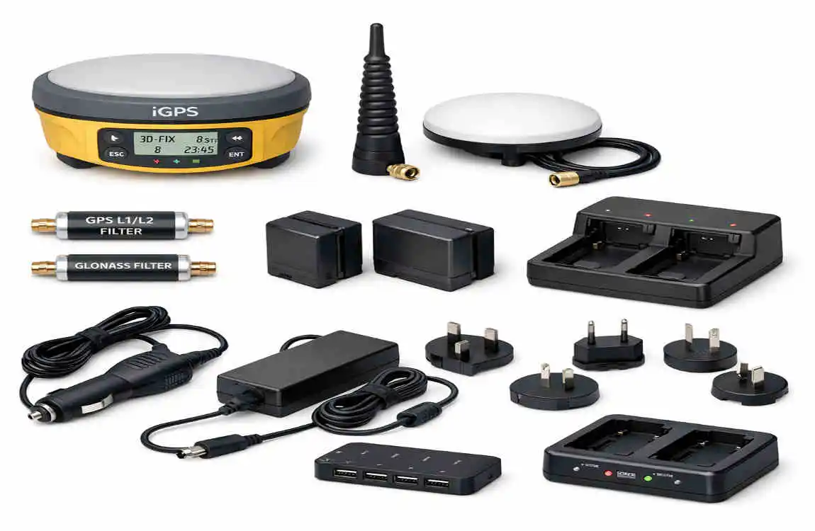
iGPS module: adding GNSS data to logged depth readings
DCI’s iGPS documentation describes iGPS as a module that attaches to the Falcon F5 receiver and adds GNSS information to logged depth readings. DCI states that the logged data can be exported as KML for Google Earth, which fits the way many contractors share job documentation—simple, readable, and map-based.
The iGPS info sheet also provides a clear spec snapshot: Product ID iGPS, operating frequency 1572 MHz, and power sourced from the Falcon F5 Receiver. It lists GNSS accuracy figures by region, including <1 m in North America (with notes) and 2–2.5 m outside North America (with notes). It also lists physical specs—8.8 x 5.7 x 1.4 in. and 0.5 lb—which matter because the module is a true field add-on, not a bench tool.
In practice, iGPS is about traceability. It helps crews tie locating data to a surface position record inside the same ecosystem they use to locate. That can support internal QA, customer documentation, and future reference—without forcing the crew to stitch together multiple unrelated devices and file formats.
Filtered antennas and inline filters: keeping telemetry stable
Telemetry is the link between the locator and the rig. When that link drops, the drill operator loses updates at the worst time. DCI’s filtered antenna information sheet explains that filtered antennas and inline filters help block RF interference at the remote display to enhance telemetry performance in high-interference environments. It lists common interference sources such as cell/radio towers, high-voltage lines, and two-way radios.
The same document also makes selection practical. It distinguishes connector types—BNC and TNC—based on display type and installation configuration. That detail helps crews avoid a familiar waste: buying the right accessory in the wrong connector. It also supports a better job habit. If you know the site is RF-heavy, plan the antenna and filter setup before the first rod, not after the first telemetry dropout.
Battery packs and charging: keeping the system powered
Battery systems decide how long the gear stays useful in the field. DCI’s Falcon F5 system sheet lists the receiver as using a lithium-ion battery pack with 8–12 hours of battery life. That range supports a typical workday—but only if crews keep packs healthy, rotate spares, and charge consistently.
DCI’s FBC F Series Battery Charger manual gives clear power requirements: AC input 100–240 V, 50–60 Hz, 1.5 A max and DC input 10–28 V, 5 A max. That flexibility matters for HDD crews because it supports shop charging and field charging from rig or vehicle power systems.
The same manual states that F Series battery packs power “current DigiTrak receivers and battery-operated remote displays.” Standardizing around the correct packs and charger reduces downtime and avoids field improvisation with mismatched power gear.
Safety and compliance notes tied to the system
HDD crews need safety guidance they can follow without decoding it. DCI’s Falcon F5 Operator’s Manual includes RF exposure guidance that calls for maintaining a minimum separation distance of 8 inches between the receiver and the user’s torso. Treat that requirement as part of normal handling. It is a condition of operating the equipment as documented.
Remote displays also carry compliance language because they operate as part of a radio telemetry system. The Aurora operator manual includes regulatory statements and RF exposure guidance consistent with radio equipment use. Mount the display and antenna with intention, and follow the manual’s safety guidance during operation—especially when the display sits near an operator for long periods.
Power equipment has its own compliance requirements. The FBC charger manual includes FCC Part 15 compliance language and warns that unapproved changes can void authority to operate. That’s plain direction: do not modify the charger and do not treat it as field-repairable unless DCI instructs you to do so.
Finally, the Falcon F5 Operator’s Manual describes pre-drill checks—such as confirming system operation and verifying performance—before each drilling run. Crews work close to existing utilities. Reliable locating data is not only a productivity issue. It is a safety issue.
Falcon F5 System Components: Receiver, Transmitter, Remote Display & Accessories – Short FAQ
What is the Falcon F5 system?
The Falcon F5 is a detection or control system (depending on application) that typically includes multiple components working together for signal transmission, receiving, and monitoring.
What is the receiver used for?
The receiver captures signals sent from the transmitter and converts them into readable data or system actions.
What does the transmitter do?
The transmitter sends signals or data from the source device to the receiver for processing or display.
What is the remote display unit?
The remote display shows real-time system information such as readings, alerts, or operational status in an easy-to-read format.
What accessories come with the Falcon F5 system?
Common accessories may include cables, power adapters, mounting hardware, protective cases, and connection modules.
How do the components work together?
The transmitter sends data, the receiver processes it, and the remote display presents the information to the user.
Is the Falcon F5 system portable?
Many versions are designed to be portable or semi-portable depending on configuration and usage needs.
Can accessories improve system performance?
Yes. Proper accessories help improve connectivity, durability, and ease of installation.
What is the main advantage of the Falcon F5 system?
The main advantage is efficient communication between components for accurate signal processing and real-time monitoring.