
A house plumbing riser diagram is one of those drawings that may look small on paper but carries a lot of weight in real life. If you are planning a remodel, applying for a permit, or helping a contractor understand how a home’s plumbing works, this drawing can save time, reduce confusion, and support smoother inspections.
At first glance, a riser diagram can feel intimidating. It shows pipes in a vertical, almost 3D way, while a floor plan stays flat and top-down. That difference matters. A floor plan tells you where things sit on a level surface. A riser diagram shows how those same pipes move up, down, and through the floors of the house. That is why inspectors, plumbers, and permit reviewers rely on it so heavily.
A clear diagram helps people see the full story of the plumbing system. They can understand where fixtures connect, how waste leaves the house, where vents travel, and whether the pipe sizes make sense. In other words, it turns a hidden system into something easy to review.
| Phase | Task | Key Details |
|---|---|---|
| Preparation | Gather Tools | Use a 30/60/90 triangle, grid paper, fixture unit tables, and pipe size charts . |
| System Mapping | Identify Connections | Locate the main water meter and the point where the building drain exits to the sewer . |
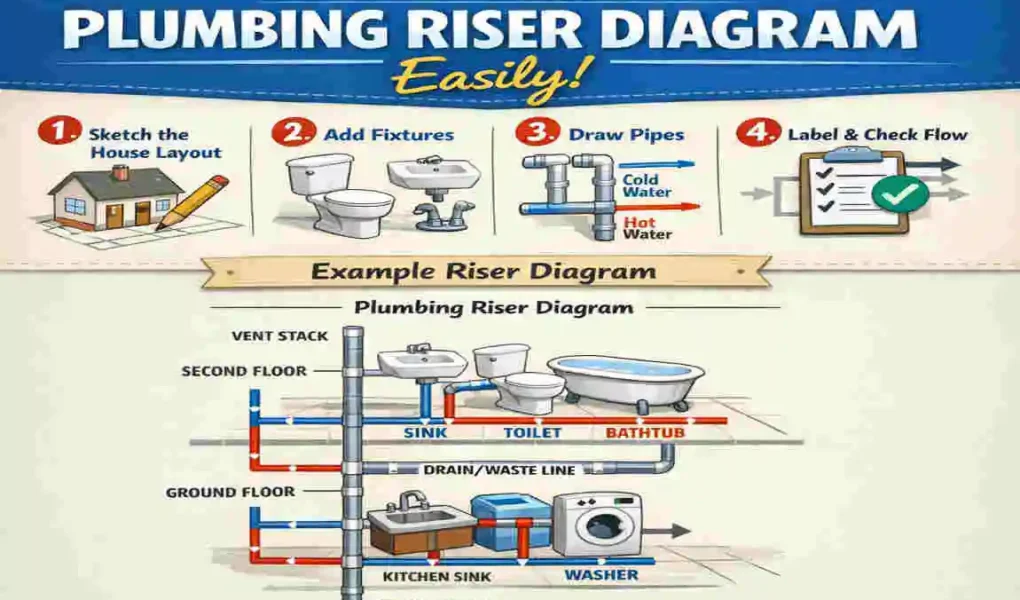
| Vertical Layout | Sketch Stacks | Map the vertical waste, vent, and supply stacks, representing floor-to-floor heights . |
| Fixture Detail | Horizontal Runs | Draw branch lines from each fixture to the main stack, including traps and vent connections . |
| Standardization | Use Symbols | Apply industry-standard symbols for valves, pipes, and fittings to ensure professional clarity . |
| Verification | Review Code | Confirm compliance with local building codes, specifically regarding wet and dry venting requirements . |
Understanding Plumbing Riser Diagrams
What a plumbing riser diagram is
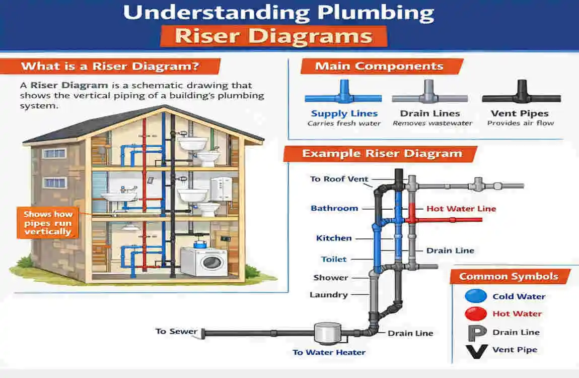
A plumbing riser diagram is a vertical drawing that shows how plumbing lines move through a building. It is often drawn in an isometric style, which means the lines are drawn to give a sense of depth. This makes the system easier to understand than a flat plan alone.
Think of it as a map of the plumbing from one floor to another. It shows how the drain, waste, vent, and sometimes water lines connect between the lowest point in the system and the fixtures on each level. It is especially useful in homes with multiple floors, basements, or complex bathroom layouts.
The riser diagram is not just a nice extra drawing. In many projects, it becomes part of the permit set. It helps the reviewer determine whether the system is safe, logical, and code-compliant. It also gives the contractor a clear reference during installation.
Why it matters for permits
Most permit offices want to know that the plumbing design follows the local code. A riser diagram helps prove that. It shows the arrangement of pipes, the connections between fixtures, and the airflow through the vent system. Without that, the reviewer may have to guess, and guessing does not help anyone.
A clean diagram can speed up approval by answering basic questions before they are asked. Where does the toilet drain go? How is the lavatory vented? Does the main line size make sense? Is the stack running through the roof correctly? When those things are visible, the permit process becomes much smoother.
It also reduces field errors. A contractor who can study the diagram before work starts is less likely to install a pipe the wrong way or miss a required vent connection.
Key parts you should include
A useful riser diagram should clearly show the main plumbing components. At minimum, you want to include:
- Stacks that carry waste vertically through the building
- Soil and waste piping that moves sewage and wastewater away from fixtures
- Vent piping that lets air enter and balances pressure in the system
- Fixture connections for toilets, sinks, tubs, showers, and other fixtures
- Cleanouts where required for maintenance and access
- Pipe sizes and fitting types where needed for review
These parts work together. The drain carries waste out. The vent keeps the system breathing properly. The fixtures connect into the system in a specific order. When you draw all of that clearly, the diagram becomes a working tool, not just a sketch.
Symbols and labels matter
A riser diagram is easier to read when you use standard symbols and labels. Pipes should be shown consistently. Fittings should be named clearly. Common fittings include sanitary tees, wyes, offsets, traps, and elbows. If the reviewer can identify the fitting quickly, they can understand the system much faster.
Labels should be simple and direct. For example, instead of writing a long note, you might label a line as 3″ soil stack, 2″ vent, or 1 1/2″ lavatory drain. That keeps the drawing clean and avoids confusion.
You do not need to decorate the drawing. You need to make it readable. That is the real goal.
Why the vertical view is so important
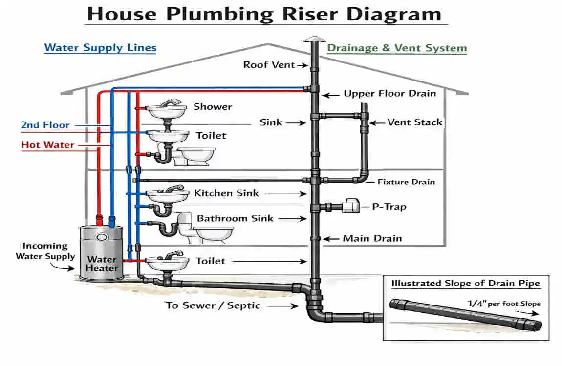
A floor plan tells you where a sink is located in a bathroom. A riser diagram shows how the sink connects to the drain below, how the vent rises above it, and how the line continues through the structure. That vertical relationship is what makes the riser diagram powerful.
If the plumbing crosses floors, the vertical view becomes even more important. You can show how a second-floor bathroom connects to a stack that continues into the basement and out to the building drain. You can also show where a vent rises through the roof and where branches join the main line.
This is why the drawing is often called a 3D isometric plumbing drawing. It helps the viewer see the system as a whole rather than as separate rooms.
Necessary Tools and Preparation
Basic drafting tools
You do not need a giant studio to start drawing a plumbing riser diagram. You can begin with a few simple tools and a clear plan.
A basic setup may include:
- Drafting paper
- Pencil and eraser
- Straightedge or ruler
- 30/60/90 triangle for isometric accuracy
- Templates for circles, fittings, or common symbols
The 30/60/90 triangle is especially useful because it helps you maintain consistent isometric angles. That matters when you want the drawing to look professional and easy to follow.
If you are working by hand, take your time with layout. A rushed sketch often creates confusion later. A neat drawing is easier to read and easier to approve.
Digital drafting options
Many people now use CAD or Revit MEP software to draw plumbing risers. These tools can save time, reduce mistakes, and make revisions much easier. If you need to update a pipe size or move a fixture, digital drafting makes that much simpler than redrawing everything by hand.
Digital tools also help you keep linework clean. You can layer fixtures, vents, and drains separately. You can copy details from one part of the design to another. You can also print the diagram in a format that is easier for permitting staff or contractors to review.
That said, software is only a tool. It does not replace code knowledge or good judgment. A perfect-looking drawing can still be wrong if the plumbing layout is not code compliant.
Reference materials you should gather first
Before you begin, gather the information that will guide the drawing. This is where many people save time later. A little preparation now prevents many corrections later.
Make sure you have:
- The local plumbing code book
- Pipe sizing tables
- Fixture unit tables
- The floor plan or architectural layout
- Any notes about existing plumbing conditions
These materials help you understand what the system must do and what the code allows. If you skip this step, you may end up drawing a system that looks fine but fails review.
The best drawings are not made by guessing. They are made by matching the layout to the actual rules and the actual building.
Essential Plumbing Code Requirements
Why code compliance is non-negotiable
When people ask how to draw a plumbing riser diagram for a house, they often focus on linework and symbols. But the real foundation is plumbing code compliance. If the drawing does not comply with local code, it may be rejected, revised, or deemed unusable.
That is why the code should shape the diagram from the start. You are not just drawing a system that looks logical. You are drawing a system that must work safely, drain properly, and pass inspection.
Codes may differ by location, so a generic drawing template is not enough. One town may have different venting rules, pipe sizing limits, or fixture requirements than another. That means you should always confirm the local version before finalizing the diagram.
A permit reviewer does not want to guess your intent. They want to see that the layout clearly meets the rules.
Dry vents and wet vents
One of the most important concepts in riser diagrams is the distinction between dry vents and wet vents.
A dry vent carries only air. It does not carry waste or wastewater during normal use. Its job is to support proper drainage by balancing pressure in the piping system.
A wet vent does more than one job. It may carry waste from one fixture while also serving as a vent path for another fixture. Wet venting can save space and simplify a layout, but it must be done correctly. If the sizes or connections are wrong, the system may not work as intended.
When you draw these lines, make sure they are easy to distinguish. A reviewer should be able to tell whether a line is only venting or serving multiple functions. If the layout is not clear, add a note or adjust the symbols so the intent is obvious.
Fittings and slab penetrations
Some fittings are allowed in certain places and not in others. That is why you should always check the code before placing a fitting in the drawing. For example, a sanitary tee may be allowed in one situation, while a wye may be better in another. The same goes for elbows and directional changes.
You should also pay close attention to slab penetrations, especially in homes with concrete floors. A pipe passing through a slab must be installed with care. The drawing should clearly reflect that, since the installation may require special attention to slope, routing, or protection.
Do not assume every fitting works everywhere. Good riser diagrams show that you understand the right fitting for the right job.
Understanding fixture unit sizing
Fixture unit sizing is one of the most important parts of plumbing design. It helps you figure out the pipe diameters needed to carry the expected load. Different fixtures create different demands. A toilet creates a different demand than a lavatory sink or shower.
This is why codes often assign fixture units to fixtures. Once you add them up, you can size the piping more accurately. If the line is too small, drainage may be slow or unstable. If it is too large in the wrong place, the system may not work efficiently.
Here is a simple example table to help you think about sizing. Always confirm the exact values with your local code, because tables can vary.
Fixture Type Typical Pipe Size Example Notes
Lavatory Sink 1 1/2″ Common for small fixture branches
Shower 2″ Often needs more capacity than a sink
Kitchen Sink 1 1/2″ or 2″ May vary based on local code and layout
Toilet 3″ Common minimum size in many residential cases
Main Building Drain 3″ or larger Depends on total load and code rules
This table is only a guide. The real sizing decision should always come from the local code and the total fixture count in the home. Still, it helps you understand why the diagram cannot be drawn casually. Pipe size is part of the design, not just a note added later.
Why sizing affects the whole drawing
Once you understand fixture units, the diagram becomes more meaningful. You are no longer just connecting fixtures with lines. You are showing how the entire system can handle the building’s load.
That affects the stack, the branch lines, the vent lines, and the main drain. If you change one part, you may need to adjust several others. That is why sizing should occur during the drawing process, not after.
Step-by-Step Drawing Process
Draft the main building drain and stack layout
Start with the system’s backbone. This is usually the main building drain and the vertical stack that serves the house.
Before drawing the fixture branches, identify where the system begins and where it exits the building. In many homes, the main drain runs below the lowest floor and carries wastewater to the sewer or septic connection. The stack rises through the floors and acts as the main vertical path for waste and venting.
At this stage, focus on the system’s large-scale movement. Ask yourself:
- Where does the main line leave the house?
- Which stack serves which group of fixtures?
- Does the stack run through more than one floor?
- Where does it terminate above the roof?
The goal here is to create the system’s skeleton. Once that is in place, the smaller branch lines can be attached in the correct order.
Keep the lines simple. You are building the structure first. Fine details can come later.
Add branch lines for each floor
Once the main drain and stack are set, begin adding the branch lines for each floor. This is where the diagram starts to resemble the actual house.
A good way to approach this is to start from the lowest point and work upward. That helps you see how the system collects waste and how the upper fixtures connect back to the main line. If the home has a basement, include those fixtures first. Then move to the first floor, and then the second floor if needed.
For each floor, locate the fixtures and connect them to the appropriate branch. A toilet may connect to one branch. A sink and a shower may be connected. If several fixtures share one line, show that clearly.
This part works best when you carefully match the floor plan. The room layout helps you place each fixture correctly, but the riser diagram shows how those fixtures connect vertically. Keep checking both views as you draw.
Integrate the vent system
The vent system is not just an extra. It is part of what makes the plumbing work properly. Without venting, the drain system can trap air, lose flow, or create pressure problems that affect fixture performance.
As you draw the vents, make sure each vent path is clear. A vent may rise from a fixture or branch, then continue upward to connect with a main vent or exit through the roof. In some systems, multiple vents combine before termination.
The key is to show the airflow path just as clearly as the waste path. A reviewer should be able to tell that a proper vent arrangement protects each fixture.
Be especially careful where vents join branches. The exact location and type of connection can matter a lot under code. If a vent is also acting as part of another fixture’s drainage path, label it clearly so the drawing does not become confusing.
Verify pipe sizes and connection types
Once the basic layout is drawn, go back and check the sizing. This is where your fixture unit table and code book become essential.
Review each branch and ask whether the pipe size is correct for the load. Then check the main drain and stack sizes. After that, confirm the connection types. Did you use the correct fitting? Did the line turn the right way? Did the vent rise in a way that makes sense?
This is also the time to add clear notes. Label pipe sizes where needed. Mark the stack. Identify the fittings. If a line changes size, show the transition clearly.
A riser diagram should not leave the reviewer guessing. If they have to study it too long, the drawing probably needs more clarity.
A simple workflow you can follow
To keep your work organized, use this basic sequence:
- Trace the main drain and stack
- Add each floor’s fixture branches
- Draw the vent lines
- Check pipe sizes with fixture units
- Label fittings, sizes, and terminations
- Review the diagram against local code
This sequence keeps the process manageable. It also helps you avoid the common mistake of adding details too early before the main structure is set.
Keep the drawing readable as you go
Clarity matters as much as accuracy. A diagram that is technically correct but visually messy can still create problems. If the lines overlap too much or the labels crowd together, the inspector may have trouble reading it.
Leave space where you can. Use consistent line weights when drawing by hand or in software. Group similar information together. If a line needs a note, place the note close enough to be useful but not so close that it clutters the drawing.
Think of the riser diagram like a conversation. It should speak clearly and directly.
Common Mistakes to Avoid
Forgetting vent terminations
One of the easiest mistakes to make is forgetting how the vent system ends. Every vent stack must terminate properly, usually above the roof and at the required height. If this is missing or unclear, the drawing may raise immediate questions.
This is not a small detail. Vent termination affects system performance and code compliance. If the line ends too low or the termination is not shown, the reviewer may assume the design is incomplete.
Always show where the vent leaves the building. If multiple vents join, keep the path clear from start to finish.
Ignoring local amendments
Many people start with a generic template and assume it will work everywhere. That is a mistake. Local plumbing rules often include amendments or special requirements that change how a system must be designed.
A drawing that passes in one place may fail in another. Pipe sizes, venting methods, and fixture arrangements can all be affected by local rules.
Before you finalise anything, check the local code carefully. Do not rely on memory alone. Do not assume last year’s project rules still apply. If the jurisdiction has an amendment, it matters.
Overcrowding the drawing
A riser diagram should explain the system, not bury it under detail. If the sheet is packed with too many notes, lines, and symbols, the inspector may have trouble reading it. That can slow down approval and increase the chance of corrections.
This is where discipline matters. Add only what is needed. Keep labels short. Use spacing wisely. Separate similar systems if the page becomes too full.
A clean drawing often gets better results than a crowded one. Simplicity helps the reviewer quickly understand your intent.
Other mistakes to watch for
There are a few more errors that show up often:
- Using the wrong fitting symbol
- Forgetting to label pipe sizes
- Drawing vents as if they were drains
- Not showing the stack through the roof
- Mixing up fixture connections between floors
These may seem small, but they can create big problems during review. A careful second look can save time later.
Professional Tips and Resources
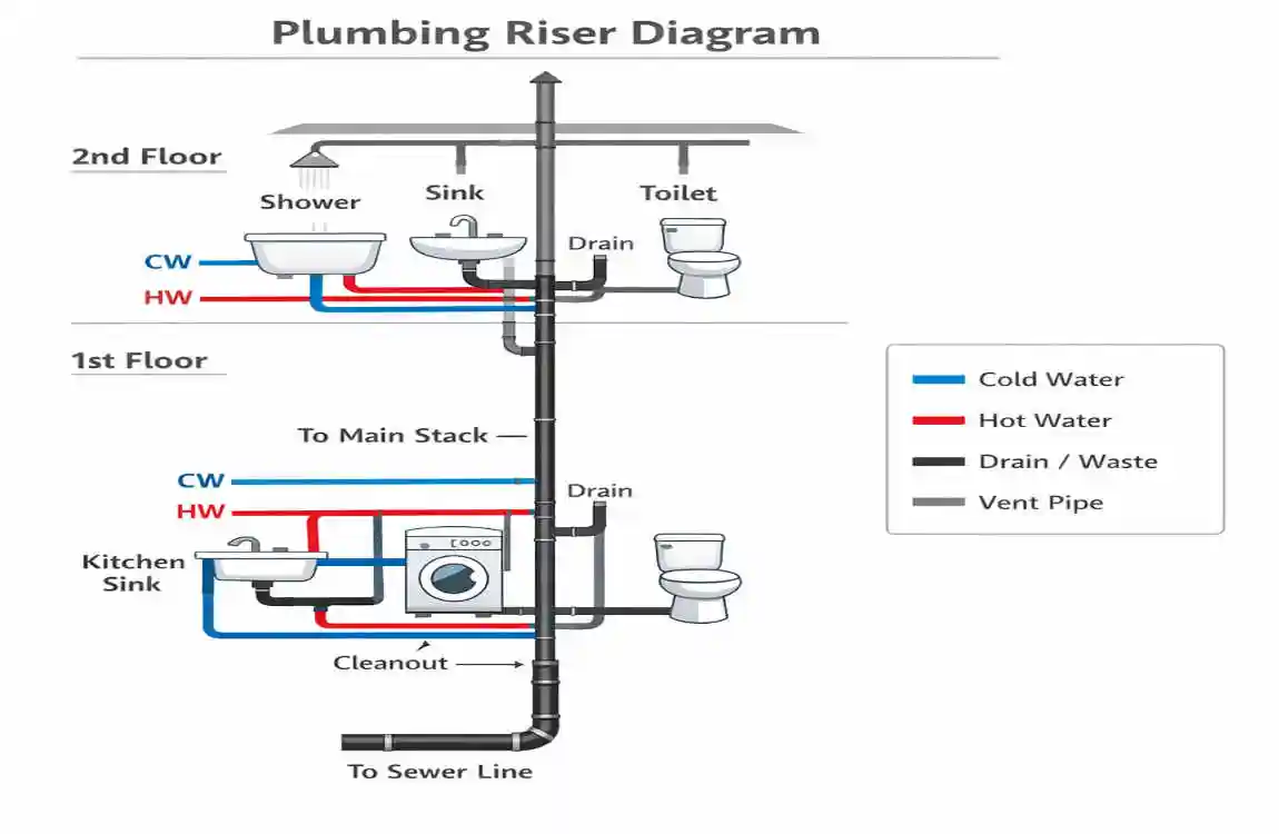
Use color coding to make the drawing easier to read
Colour coding can be very helpful, especially when a system includes multiple line types. For example, you might use one color for hot water, another for cold water, and a third for drain lines. That makes the system easier to understand at a glance.
Just keep the colors consistent. If blue means cold water on one part of the drawing, it should mean cold water everywhere else too. Consistency matters more than style.
If you are submitting a permit set, make sure the colors still print clearly in black and white if needed. A drawing should still work even when color is lost.
Use standard templates to save time
Industry-standard templates can speed up your workflow. They help you place titles, labels, and symbols in a familiar layout. That can reduce mistakes and make future revisions easier.
Templates are especially useful if you often draw plumbing diagrams. Instead of starting from scratch every time, you can build from a trusted format and adjust it to the project.
Still, do not let a template do your thinking for you. Every house is different. The layout, fixture count, and code requirements must always guide the final drawing.
Know when to call a licensed professional
Not every plumbing layout is simple. Some homes have stacked bathrooms, special venting conditions, long runs, or unusual drainage challenges. In those cases, it is smart to bring in a licensed plumber or engineer.
This is especially important if the project has multiple floors, complex remodel changes, or uncertain existing conditions. A professional can help verify code issues, sizing, and connection details before the drawing is submitted for permit.
That does not mean you cannot draft the diagram yourself. It simply means that some systems require an expert review before moving forward.
Supporting content that can make your work stronger
If you are building a full guide or design package, these extras can help:
FeatureImportance
Fixture Unit Table Helps with accurate pipe sizing and load checks
Isometric Drafting Makes 3D pipe relationships easier to understand
Code References Supports permit compliance and reduces revisions
These tools enhance your drawing. They make the project easier to review and more trustworthy.
FAQ: How to Draw a House Plumbing Riser Diagram
Q: What is a house plumbing riser diagram?
It is a not-to-scale isometric or elevation-style drawing that shows how the house’s drain, waste, vent, and water lines connect through the building.
Q: Why do I need one?
Most building departments require a plumbing riser diagram for permits, especially when new water or drain lines are being installed.
Q: What should I show on the diagram?
Show the pipe routes, fixture connections, pipe sizes, and cleanouts, along with the drain, vent, and water lines.
Q: How do I draw the lines clearly?
A common convention is to show water and waste pipes as solid lines and vents as dotted lines.
Q: Do I need code knowledge to draw one correctly?
Yes. You need a solid understanding of plumbing waste and vent systems and your local rulebook/code requirements to make a diagram that will pass review.
Q: Is it easy to draw?
No, it is usually not easy to draw well because the layout must be clear, accurate, and permit-ready.