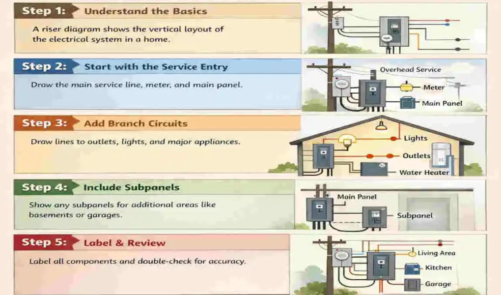
If you are planning a bathroom remodel, building a new home, or simply trying to figure out why your upstairs shower is leaking into your downstairs kitchen, you need to understand your home’s plumbing layout. Residential plumbing systems are complex networks. Planning them correctly matters immensely.
When you map out your pipes, you directly impact water flow, drainage efficiency, and the overall success of your home construction. A poorly planned system leads to low water pressure, slow drains, and expensive repairs. This brings us to a vital question: what is a riser diagram plumbing?
| Step | Action | Key notes |
|---|---|---|
| 1 | Define scope and system type | Decide plumbing or electrical riser, levels served, and which fixtures/devices to include. |
| 2 | Gather references | Collect floor plans, fixture locations, load schedules (fixture units or electrical loads), and code requirements. |
| 3 | Choose diagram orientation | Draw vertical elevation (riser) left-to-right or top-to-bottom; show floors and service entry points. |
| 4 | Place main stacks and mains | Mark soil/waste stacks or electrical bus and main service entry, indicating pipe/cable sizes. |
| 5 | Add branches and fixtures | Draw branch lines from mains to each fixture or panel; show fixture names and quantities. |
| 6 | Indicate flow/vent directions | Use solid lines for flow (drains, hot/cold, conductors) and dashed lines for vents or control wiring; add arrows. |
| 7 | Label sizes and ratings | Annotate pipe diameters, wire gauges, amp ratings, and fixture unit or load values next to each run. |
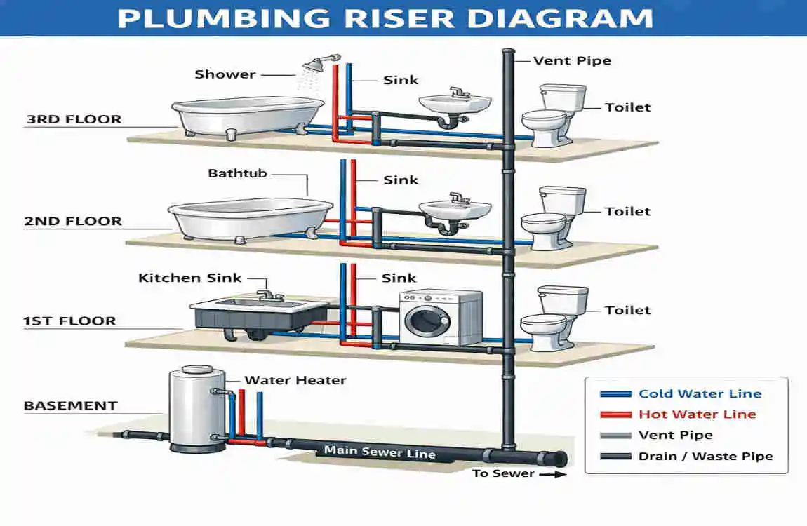
In simple terms, a plumbing riser diagram is a vertical map of your home’s pipes. It shows exactly how water travels up to your fixtures and how waste travels down and out. This visual tool is essential for anyone involved in building or fixing a house.
What Is a Riser Diagram in Plumbing?
Definition and Basic Explanation
So, what is a riser diagram plumbing exactly? Imagine you could magically slice your house in half from the roof to the foundation and look at the pipes inside the walls. That vertical view is exactly what a riser diagram provides.
It is a two-dimensional, vertical representation of your plumbing system. Instead of looking down at your house from above, you look at it from the side. This diagram illustrates how pipes, fixtures, and water lines connect across different floors.
Purpose of a Plumbing Riser Diagram
A plumbing riser diagram serves as a powerful visual planning tool. Before anyone cuts a single pipe, this diagram shows exactly where every piece goes.
It helps tremendously during installation, providing plumbers with a clear roadmap to follow. Later on, it simplifies maintenance and repairs. If you leak, the diagram helps you pinpoint the exact vertical pipe that may be causing it. Most importantly, inspectors use this plumbing layout diagram to ensure your home meets local safety and health codes.
Difference Between Riser Diagrams and Floor Plans
You might wonder how this differs from a standard blueprint. The main difference lies in the perspective. A floor plan is a horizontal layout. It shows where your sink is located in the room, but it does not show how the water gets up to that sink.
A riser diagram focuses on the vertical layout. It highlights differences in pipe routing between floors. Crucially, it provides visibility for drainage and venting systems, which rely heavily on vertical drops and upward airflows.
Think about a plumbing setup for a two-story home. A floor plan shows a bathroom right above the kitchen. The riser diagram, however, shows the actual pipe (the riser) traveling straight up from the kitchen ceiling, through the floor joists, and connecting to the upstairs toilet and shower.
Why Riser Diagrams Are Important for Homes
Benefits for Homeowners
For homeowners, having a residential plumbing diagram is like holding the cheat sheet to your house. It gives you a much better understanding of your plumbing layout.
If you decide to finish your basement or add a new bathroom, having this diagram makes renovations and upgrades much easier. You will know exactly where you can tap into existing water lines. Furthermore, if you notice a sudden water stain on your ceiling, a riser diagram helps you detect leaks more quickly by showing which pipes run directly above the stain.
Benefits for Plumbers and Contractors
Professionals absolutely rely on the house plumbing design shown in a riser. It provides accurate installation guidance, removing the guesswork from the job.
When a plumber looks at a well-drawn diagram, it creates improved communication between the plumbing team and the general contractor. Everyone knows where the pipes are going, which leads to heavily reduced construction mistakes. You certainly do not want a contractor driving a nail into a hidden vent pipe!
Building Code and Permit Advantages
If you are doing major work, you cannot escape the permit office. A plumbing system diagram is strictly required in many permit applications.
City officials and inspectors use these diagrams to review your planned systems. They look for specific details, such as water-efficiency measures, proper drainage planning, and correctly positioned vent stacks. Without a clear riser diagram, your project will likely be delayed or rejected at the permit desk.
Main Components of a Plumbing Riser Diagram
When you look at a plumbing stack diagram, you will see a web of lines and shapes. Let’s break down the main components you will encounter.
Water Supply Lines
First, you have your incoming water. The diagram will clearly separate the hot and cold water pipes, often using different line styles or labels.
It will also cover basic pipe sizing. This is crucial because a pipe that is too narrow will cause low water pressure. The diagram accounts for pressure considerations, showing thicker pipes near the water main that branch into smaller pipes at the individual sinks.
Drain-Waste-Vent (DWV) System
The drain, waste, and vent system is the unsung hero of your home. It handles all the dirty work. The diagram will map out the drain lines that carry water away from sinks and showers.
It also highlights waste pipes, which specifically carry waste from toilets. Finally, it shows the vent stacks. These are the pipes that go up through your roof, allowing air into the system so the water drains smoothly without gurgling.
Fixtures Shown in Riser Diagrams
A good diagram doesn’t just show pipes; it shows what those pipes connect to. You will see representations of:
- Toilets
- Bathroom and kitchen sinks
- Showers and bathtubs
- Washing machines
- Water heaters
Pipe Symbols and Plumbing Notations
To keep the drawing clean, professionals use standard plumbing symbols rather than drawing realistic pipe images.
You will see directional arrows indicating the direction the water flows. You will also see pipe-diameter labels, indicating exactly how wide the pipe needs to be at any given point.
Vertical Stacks
Because a riser diagram is vertical, the “stacks” are the stars of the show.
- Soil stack: Carries human waste from toilets down to the sewer.
- Vent stack: Carries sewer gases up and out of the house.
- Main riser: The primary vertical pipe delivering clean water upward to the different floors.
Quick Component Reference
ComponentFunctionCommon Materials
Supply Pipes Deliver fresh, pressurized water to fixtures Copper, PEX, CPVC
Drain Pipes Remove wastewater using gravity PVC, ABS, Cast Iron
Vent Pipes Balance air pressure and exhaust gases PVC, ABS
Types of Plumbing Riser Diagrams Used in Homes
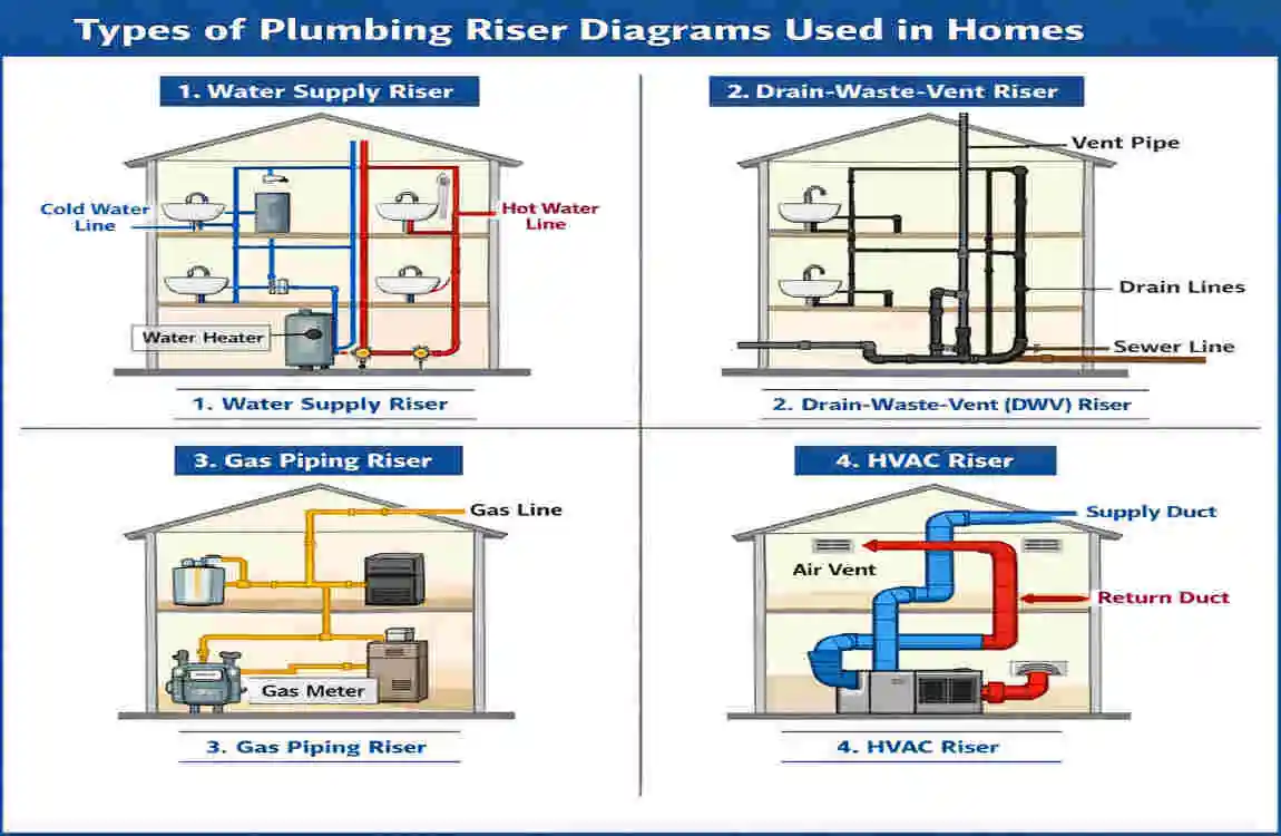
Not all diagrams are created equal. Depending on the complexity of your project, you might encounter different types of riser diagrams.
Water Supply Riser Diagram
This specific diagram focuses purely on incoming clean water. It tracks the water from the municipal meter or well pump, through the water heater, and up to every hot and cold faucet in the house. You use this when mapping out water pressure and supply distribution.
Drainage Riser Diagram
A drainage plumbing layout focuses solely on wastewater movement and ignores clean water. It shows every P-trap under your sinks and how they connect to the main downward soil stacks.
Venting Riser Diagram
Often paired with the drainage diagram, the plumbing vent diagram focuses entirely on airflow and pressure regulation. It shows how the pipes rise to the roof, preventing harmful sewer gases from entering your living spaces.
Combined Plumbing Riser Diagram
For most residential projects, a combined diagram is used. This provides a full system overview on a single page, showing supply, drainage, and venting together.
In simple residential homes, a combined diagram is usually sufficient. In massive commercial applications such as high-rise apartments, these systems are so complex that engineers must split them into separate diagrams to make them readable.
Tools and Materials Needed to Create a Plumbing Riser Diagram
You do not need to be a professional architect to draw a riser diagram, but you do need the right tools.
Traditional Drafting Tools
If you prefer to work by hand, traditional drafting tools work perfectly fine. You will need:
- A pad of grid or graph paper to keep your lines straight.
- A sharp pencil and a sturdy ruler.
- Plumbing templates (small plastic stencils that help you draw standard fixture shapes).
Digital Software Options
For a cleaner, more professional look, many turn to plumbing design software. These programs automatically snap lines together and calculate pipe lengths. Popular options include:
- AutoCAD: The industry standard for professional plumbing drafting tools.
- SmartDraw: A very user-friendly option for beginners.
- Revit: Advanced 3D modeling software used by architects.
- EdrawMax: Excellent riser diagram software with pre-made plumbing templates.
Measurements and Data Required
Before you draw a single line, you need hard data. You must know the exact locations of your fixtures. You need to determine your required pipe sizes. You also need accurate floor heights to determine exactly how tall your vertical risers must be, and to lock in your water heater placement.
Bonus Tip: The absolute most important step before you start designing is checking your local plumbing codes. Rules change from city to city, and your diagram must reflect local laws!
Step-by-Step Guide to Creating a Plumbing Riser Diagram for Homes
Are you ready to create your own home plumbing planning guide? Follow these nine simple steps to learn how to draw a plumbing riser diagram.
Study the Floor Plan
Start by grabbing your home’s horizontal floor plan. Identify all the “wet” rooms: bathrooms, kitchens, laundry rooms, and utility rooms. Mark the exact fixture positions. You need to know exactly where the toilet sits on the second floor compared to the kitchen sink on the first floor.
Determine Main Water Supply Entry
Next, figure out where your water comes from. Locate the water meter and the main shut-off valve on your property. From there, plan your distribution lines. Map out how the cold water will travel to the water heater, and how both hot and cold lines will branch out vertically to your wet rooms.
Identify Drainage Routes
Now, think about gravity. Wastewater relies entirely on gravity-based drainage planning. Water flows downhill, so your pipes must too. Learn the basics of proper pipe slope: horizontal drain pipes usually need to slope downward at 1/4 inch per foot. Map out how the drains from the upper floors will drop straight down into the main sewer line.
Add Vent Pipes
Every drain needs a vent. Without vents, water draining from a toilet could suck the water out of a nearby sink trap, allowing foul odors into your house. Add vent lines to your drawing that run upward and penetrate the roof. This will prevent sewer gases and maintain a perfect airflow balance.
Draw Vertical Pipe Connections
This is the core of the plumbing riser diagram steps. Connect your upper and lower floors using vertical lines. Ensure your stack alignment is logical. You want your vertical pipes hidden within the walls, so align them with your home’s architectural features.
Label Pipe Sizes and Materials
A line on a page is useless to a plumber without context. Add your diameter notation. Label the main water line as 3/4-inch, branching down to 1/2-inch for sinks. Include the material specification. Write “PVC” for your drains and “PEX” or “Copper” for your supply lines.
Add Plumbing Fixtures
Now, attach the fixtures to your pipe network. Draw the symbols for:
- Toilets
- Sinks
- Showers
- Appliances like dishwashers and washing machines
Make sure you clearly show both the hot/cold supply lines entering the fixture and the drain line exiting it.
Review Local Plumbing Codes
Take a pause and review the rulebook. Check your local laws regarding vent sizing and pipe distance rules. Some cities strictly dictate how far a sink can be from a main vent stack. Ensure your drawing meets all local inspection requirements so you pass your permit check on the first try.
Finalize and Test the Layout
Take a step back and trace the lines with your finger. Double-check all connections. Does the hot water actually reach the upstairs shower? Does the upstairs toilet drain directly into the main sewer without crossing a supply line? Ensure the overall readability is clear and easy for anyone to understand.
Imagine a practical example of a two-story home riser diagram: You trace the 3/4-inch supply line from the basement up through the first-floor wall, splitting off 1/2-inch lines to the kitchen sink, before continuing upward to feed the master bathroom on the second floor. Simple, logical, and highly organized!
Common Mistakes to Avoid When Designing Plumbing Riser Diagrams
Even with a solid plan, plumbing design mistakes happen. Here are the most common pitfalls to avoid.
Incorrect Pipe Sizing
If you draw pipes that are too small, you will experience severe water pressure issues. Imagine turning on the shower and only getting a trickle because someone flushed the toilet! On the flip side, incorrect pipe sizing on drains leads to constant drainage blockages.
Poor Vent Placement
Plumbing venting errors are incredibly common for beginners. If you place a vent too far from a trap, you will experience slow drainage and a constant, unpleasant smell of sewer gas in your home.
Ignoring Local Plumbing Codes
Your city’s building codes exist for your safety. Ignoring them leads to failed inspections. A failed inspection means you have to tear down drywall and redo the plumbing, which can result in incredibly expensive repairs.
Overcomplicated Layouts
Keep it simple. Do not route pipes in zig-zags just to save a few inches of material. Overcomplicated layouts result in hard-to-maintain systems. If a plumber has to fix it 10 years from now, a straight, logical path is always best.
Missing Fixture Labels
Never assume a drawing is self-explanatory. Missing fixture labels create massive confusion during installation. Always clearly mark what each symbol represents.
Understanding Plumbing Symbols in Riser Diagrams
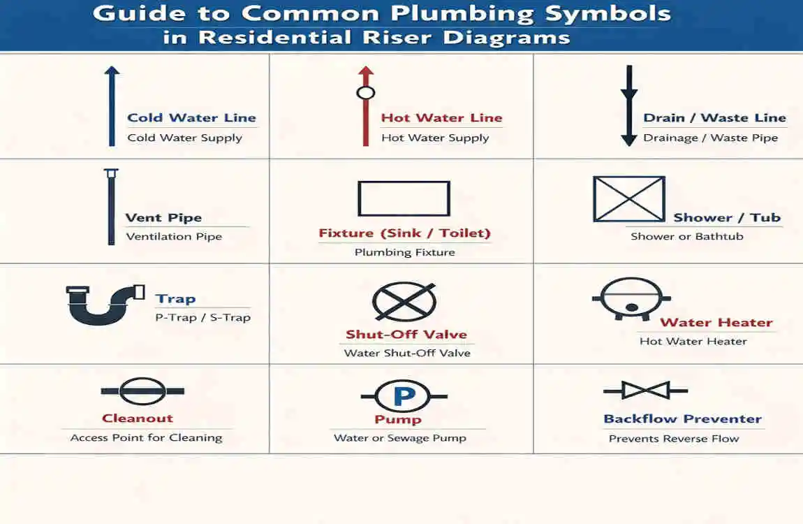
To read and write these diagrams effectively, you need to understand the language of plumbing blueprint symbols.
Common Symbols Explained
Instead of words, riser diagram symbols quickly communicate complex parts.
- Valves: Usually depicted as triangles pointing at each other. They show where water can be shut off.
- Cleanouts: Essential for clearing clogs, marked to show access points in the drain.
- Water heater: Often shown as a large circle or rectangle with “WH” inside.
- Vent stack: Displayed as lines going up through a horizontal roofline.
- Floor drain: A circle with grid lines inside it.
Reading Pipe Line Types
The lines themselves tell a story.
- Solid lines: Typically represent cold water supply or main drain lines.
- Dashed lines: Almost always represent hot water lines or hidden vent pipes.
- Direction arrows: These are crucial. They show exactly which way the water or waste is flowing.
Why Symbols Matter
You might wonder why we don’t just use words. The reason is universal understanding. A standard set of plumbing diagram symbols means a plumber from any state can look at your drawing and instantly know what to do. This leads to a much faster, safer construction workflow.
Quick Symbol Reference
SymbolMeaning
Circle with a cross Drain / Floor Drain
Two Triangles meeting Shut-off Valve
Solid Line Cold Water Supply / Drain
Dashed Line Vent Pipe / Hot Water
Arrow Direction of Flow
Plumbing Codes and Safety Standards for Residential Riser Diagrams
A pretty drawing is useless if it is illegal. You must adhere strictly to residential plumbing codes.
International Plumbing Code (IPC)
Most of the United States follows the general provisions of the International Plumbing Code (IPC). The IPC dictates the minimum standards for safe plumbing installations, covering everything from the thickness of PVC pipes to the maximum temperature of water heaters.
Uniform Plumbing Code (UPC)
Depending on where you live, you might fall under the Uniform Plumbing Code (UPC). It is important to know the regional differences. The UPC is often considered slightly more strict, particularly regarding pipe sizing and venting, and is heavily used in western states.
Safety Considerations
Codes exist to keep you safe. Your diagram must account for backflow prevention, ensuring dirty water cannot accidentally siphon backward into your clean drinking water. You must also ensure proper pipe support spacing to prevent pipes from sagging and breaking over time. Finally, strict ventilation standards prevent combustible sewer gases from accumulating in your walls.
Permit and Inspection Process
This is why inspectors rigorously review diagrams. The plumbing permit requirements require a riser diagram because it is the easiest way for an inspector to verify that you have complied with all safety standards before construction begins. Treat your inspector’s plumbing inspection checklist as your ultimate grading rubric.
DIY vs Hiring a Professional for Plumbing Riser Diagrams
Now that you know how much work goes into this, you face a choice. Should you draw this yourself or hire a professional plumber?
DIY Advantages
Creating your own diagram offers obvious cost savings. Furthermore, engaging in DIY plumbing planning gives you an incredibly intimate understanding of your home’s systems. You will know your house inside and out.
DIY Limitations
However, DIY has limitations. The biggest hurdle is code compliance challenges. Professional codes are hundreds of pages long and hard to interpret. A small design error by a homeowner can result in thousands of dollars in water damage down the line.
Benefits of Hiring Professionals
Opting for professional plumbing design offers significant peace of mind. Professionals provide perfectly accurate calculations for pipe sizing and flow rates. Because their drawings are perfect, you get much faster approvals from the city permit office. Furthermore, they use professional-grade software that is highly detailed and easy to read.
Suggested Advice: If you are tackling a small renovation—like adding a single sink to a basement—you can likely handle the DIY diagram. But if you are doing a full bathroom addition or a new home construction, getting professional help is absolutely worth the investment.
Frequently Asked Questions (FAQ)
What is a riser diagram plumbing?
A plumbing riser diagram is a two-dimensional, vertical representation of a building’s plumbing system. It shows how water supply pipes rise to fixtures and how drainage and vent pipes descend and spread outward, providing a side-view map of the system.
Is a plumbing riser diagram required for permits?
Yes, in most municipalities, a riser diagram is mandatory for any major plumbing work, new construction, or significant remodels. It proves to the city that your design is safe and up to code.
Can homeowners create their own plumbing riser diagrams?
Absolutely. Homeowners can draw their own diagrams using graph paper or accessible design software. However, they must take the time to learn local plumbing codes to ensure their drawings pass official inspections.
What software is best for plumbing riser diagrams?
For professionals, AutoCAD and Revit are the industry standards. For homeowners and DIYers, more accessible programs like SmartDraw, EdrawMax, or even SketchUp offer great templates and user-friendly interfaces.
What is the difference between a riser diagram and an isometric drawing?
A riser diagram is a flat, 2D vertical view showing the elevation of pipes. An isometric plumbing diagram is drawn at a 30-degree angle to create a 3D illusion, showing length, width, and height simultaneously, making complex spatial relationships easier to understand.
How much does a professional plumbing riser diagram cost?
Costs vary wildly based on the project’s scope. For a simple residential bathroom addition, a drafted plan might cost a few hundred dollars. For a complete new home build, comprehensive plumbing plans can range from $500 to over $1,500.
Are plumbing riser diagrams necessary for small homes?
Yes. Even a tiny home or a small cabin requires proper venting, drainage slopes, and correctly sized pipes. A riser diagram ensures that even the smallest spaces remain free of leaks, sewer smells, and low water pressure.